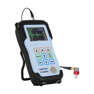
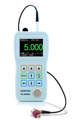
Waveform B Scan Single And Dual Element Color Screen Wall Ultrasonic Thickness Gauge
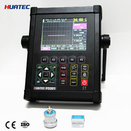
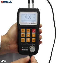
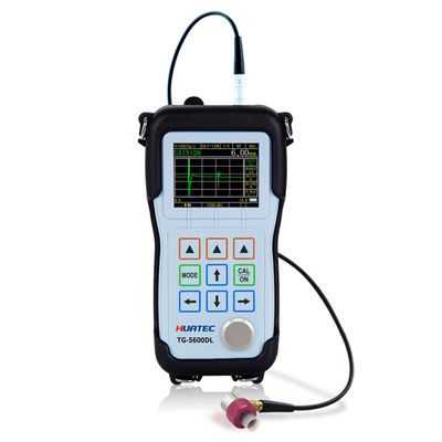
HUATEC TG-5600DL is a portable ultrasonic thickness gauge. Based on the operating principles of ultrasonic measurement, TG-5600DL is capable of measuring the thickness of various materials with accuracy as high as 0.001 millimeters or 0.0001 inches, and widely used in a variety of thickness measurement applications.
Users can measure the thickness from only one side of the material being measured, without damaging the workpiece.
TG-5600DL can display thickness readings and A-scans at the same time, allowing users to check waveforms. The echo display helps users control the measurement, so that the thickness measurement range is large, the measurement values are correct, and material-related errors in measurement can also be avoided. The B-scan function is used to observe the bottom profile of the workpiece being measured. The probe moves along the surface of the workpiece to display the cross-section of the workpiece.
This gauge can be used in manufacturing, metal processing industry, aerospace, railway transportation, chemical industry, commodity inspection industry and other testing fields.In addition to accurately measuring a variety of plates and processed parts, monitoring a variety of pipes and pressure vessels that in production equipments to further monitor their thinning levels after being corroded during use, which is an indispensable tool in the non-destructive testing industry.
The storage function is optional, according to the different needs of customers, and built-in large-capacity data logger can store up to 100,000 thickness measurement values and 400 waveforms. Other more functions can be optional, such as multi-layer thickness measurement, ultra-high resolution, large-range thickness measurement,digital noise reduction and window mode, inner wall oxide layer, real-time communication, multi-channel and other options.
Main Measurement Functions
• Most material measurements can be made using single element transducers.
• Measuring thickness range: 0.01 mm ~ 38 m, depending on the material being measured, probe, surface conditions, temperature and selected configuration.
• Determine the sound velocity of an unknown sound velocity material
• High resolution: Regular display resolution is 0.001mm, optional ultra-high resolution can reach 0.0001mm.
• Measurement units: millimeters, inches, microns and mils.
• High temperature measurement: temperatures up to 500°C.
• System default configuration menu: For user convenience, it has been set according to the default conditions for using the probe of the instrument.
• Pause function: allows post-measurement processing operations. Conveniently adjust all parameters to obtain stable measurement data.
• Full-screen waveform display function: increases the echo display area by 20%, giving the operator a large window experience.
• Echo intensity indication: The stronger the echo, the more indicator bars are displayed, especially the digit display, which is more useful.
• Time-based B-scan mode: It is used to observe the bottom profile of the workpiece to be measured.
• Difference/Reduction Rate Mode:The thickness difference relative to the set point is displayed and expressed as a percentage of the reduction rate.
• TDG time-varying gain: The initial pulse or interface echo can be effectively reduced by reducing the initial gain, and the bottom echo of the tested sample can be increased by increasing the maximum gain, which is easy to measure.
• Measurement Mode:Pulse-Echo(P-E),Interface-Echo(I-E),Echo-Echo(E-E),Multiple echo(I-ME),Double echo verification(E-EV)
Main Parameters
| Instrument Specifications |
| Working principle |
P-E (Pulse-Echo), I-E (Interface-Echo), E-E (Echo-Echo), I-ME(Multiple Echoes), E-EV(Echo verification) |
| Probe Type |
Delay line probe, Contact probe, Membrane probe, Pencil type probe, Immersion probe |
| Calibration |
Probe zero, Calibrate velocity, 1-Point calibration, 2-Point calibration, Set Velocity |
| Thickness Range |
0.01mm~38m,Depending on the tested material, probe surface conditions, temperature, and selected configuration.
0.15mm~30mm(Standard D15A probe,steel)
|
| Material velocity range |
310 - 18699m/s,and can measure the velocity with known thicknes |
| Resolution |
Optional 0.1/ 0.01/0.001mm |
| Probe Frequency |
0.5MHz~20 MHz |
| Measuring Unit |
mm, inch,μm,mil |
| Update Rate |
4HZ, 8HZ, 16HZ per second optional |
| Power Off |
Automatically power off when idle for 5,10 or 20 minutes, or manually |
| Display Type |
2.4 in (320 × 240 dot matrix)TFT color display LCD screen |
| Rectification Mode |
RF, RF-, FULL, HALF+, HALF |
| View Mode |
A-SCAN, B-SCAN, DIGITS, CAPTURE, DIFFERENCE, ALARM |
| Storage |
Can store 100,000 thickness values and 400 parameter setting files(Optional) |
| Gain |
Low, Medium or High for varying test conditions |
| Display Mode |
Normal, Minimum / Maximum capture, DIFF/RR% |
| V-Path Correction |
Automatic |
| Update Rate |
Selectable 4Hz, 8Hz, 16Hz |
| Material Velocity Range |
500 to 9999m/s (0.0197 to 0.3937in/us) |
| Languages |
Selectable Chinese, English, Japanese |
| Alarm Settings |
Minimum and Maximum alarms. Range of 0.25 mm to 508 mm (0.010" to 20.00"). Dynamic waveform color change on alarm |
| Power Requirements |
2 AA size batteries |
| Operating Time |
Approximately 40 hours |
| Instrument Shut-off |
Selectable ALWAYS ON or AUTO OFF after 5, 10, 20 minutes of inactivity |
| Operating Temperature |
-10°C to +50°C (+10°F to +120°F) |
| Size |
153mm X 76mm X 37mm(H X W X D) |
| Weight |
280g including batteries |
Standard Configuration
| Items |
Quantity |
|
TG-5600DL
Ultrasonic Thickness Gauge
|
1 |
| Probe |
1 |
| Cable |
1 |
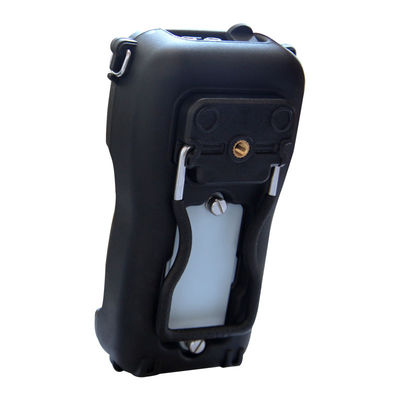
| Rubber Sheath |
1 |
| Alkaline Batteries |
- |
| Couplant Bottle |
1 |
| Case |
1 |
| Operation Manual |
1 |
| Calibration Certificate |
1 |
Optional accessories
| Probes |
Cables |
| Rubber Sheath |
Step Blocks |
| Delay Lines |
Coupling Agent |
| Protective film |
Software Options |
Appendix A: Material Velocity
The table lists the propagation velocity of ultrasond in various common materials. It is only for reference. The actual velocity of these materials may differ from the velocity in the table for various reasons, for example, material composition, preferred orientation of grains, porosity, and temperature etc. Therefore, to achieve the best measurement accuracy, a sample made of a specific material should first be tested to confirm the velocity of specific material.
Table:Material Velocity List
| Material |
Velocity(m/s) |
| Steel 20# |
5891 |
| Aluminum |
6320 |
| Chromium |
6200 |
| Copper |
4660 |
| Gold |
3251 |
| Iron |
5930 |
| Lead |
2160 |
| Magnesium |
5806 |
| Silver |
3607 |
| Titanium |
6098 |
| Zinc |
4193 |
| Tungsten |
5181 |
| Tin |
3320 |
| Brass |
4380 |
| Grey Cast Iron |
4600 |
| Glass |
5766 |
| Nylon |
2610 |
| Stainless Steel 304 |
5334 |
| PVC |
2392 |
| Silicon |
9620 |
| Quartz Glass |
5655 |
Note:Above table is for reference only. For actual velocity calibration, refer to 6.2 velocity calibration

 Your message must be between 20-3,000 characters!
 Please check your E-mail!
  Your message must be between 20-3,000 characters!
 Please check your E-mail!
