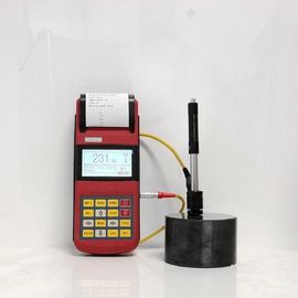
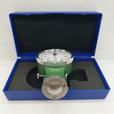
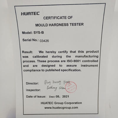
DIN 53505, ISO 868, ISO 7619 Pressure 180g Digital High Pressure Mould Wet Mould Surface Hardness Tester HT-6710C
1. Overview
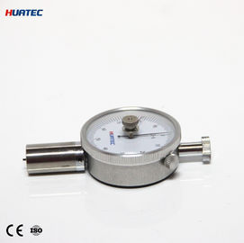
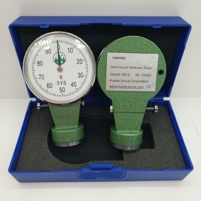
Three types of sand surface hardness testers, A B C, are used to measure the surface hardness of green sand molds.
Its structure is composed of rack pressure head (1) meter head (2) watch case (3) force spring (4) drive gear (8) rotary gear (14) pointer (15) adjusting ring (16) and so on.
Type A: Suitable for surface hardness testing of fine sand molds (cores) molded by hand or mechanical low and medium pressure.
Type B is suitable for surface hardness testing of fine and coarse sand molds (cores) molded by hand or mechanical low and medium pressure. Type C is suitable for testing the surface hardness of sand molds in high pressure molding.
2. Technical specifications and parameters
I Precision
When the pointer is any value, the corresponding force tolerance of the indenter is ±5%
The pointer returns to the O position and the tolerance is +-1 degree.
II Dimensions 90x55x28
Note: The maximum load is the force required to press the indenter to the level of the gauge head (2).
| Parameters |
Type A |
Type B |
Type C |
| Compression stroke |
2.50mm |
2.50mm |
2.50mm |
| Maximum load |
237g |
980g |
1500g |
| Preload |
90g |
50g |
180g |
| Indenter shape and size |

|

|

|
3. Principle
According to the principle that the force of the spring and the stroke are linear, the stroke of the spring is indicated by the surface pointer through a set of gears and racks. The unit of sand surface hardness is (g/mm2), but it is customary to use hardness instead of unit. Because their values are related and consistent, that is, if the unit value is large (g/mm2), the corresponding degree value is also large.
4. Use and adjustment
I Adjust the O position. When the pointer (15) is not at the O position, turn the adjustment ring (16) to align the pointer (15) with the O position. II When using, press the hardness tester firmly on the tested sand surface (the axis of the hardness tester should be perpendicular to the surface of the sand mold), so that the surface of the hardness tester head (2) is in close contact with the tested sand surface, and the pointer is also When it stops at a certain value, press the locking pin (18) to lock it, read the measured value, and then loosen the locking pin (18) to return the pointer (15) to the O position.
III When measuring, you can test 3-5 times on each measuring part, and then calculate the average number, which is the hardness value of the part.
5. Repair and maintenance
I. Do not open the watch cover (13) and the screws on the back of the watch case at will to prevent sand and dust from falling into it, which will affect its accuracy.
II. When used or placed, it is not subject to severe vibration to prevent the instrument from malfunctioning and affecting use.
III. If there is sand in the gap between the indenter (1) and the meter head (2), carefully unscrew the 3~M2 screws, remove the meter head, remove the sticky sand, and install it as it is (do not pull out the indenter)

1. With rack indenter 2. Header 3. Watch case 4. Force counter spring 5. Adjust the screw 6. Nail sets 7. Hairspring 8. Transmission gear 9. Guide pin 10. Press plate 11. Elastic cushion 12. Surface 13. Watch cover 14. Slewing gear 15. Pointer 16. Adjustments 17. Wire buckle 18. Locking pin 19. Positioning insert 20. Spring

 Your message must be between 20-3,000 characters!
 Please check your E-mail!
  Your message must be between 20-3,000 characters!
 Please check your E-mail!
