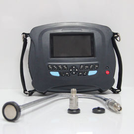
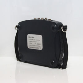
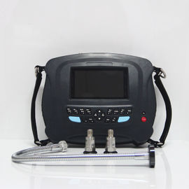
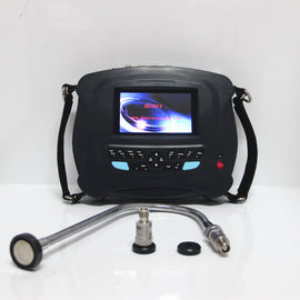
2 Channel Data Collector / Analyzer / Balancer HG904 Data Collector Transfer Function Analysis
Imbalance is one of the main causes of machine vibration. It is estimated that about 50 percent of all the faults are caused by imbalance of rotors. The best mean for getting rid of mechanical imbalance is on-site balancing. HG904 Machinery Analyzer/Balancer is especially useful for this purpose. It can measure the intensity of the vibration; diagnose vibration cause by analyzing the frequency spectrum. It can also be used to measure the rotation speed and vibration phase, and to calculate the imbalance weight and location.
Features:
- Easy to use
- Vector illustration, the balancing process and result are shown clearly at a glance
- Storage of 10 rotors balancing data
- Selectable of trial mass remove or remain
- Decompose of balancing result to two assigned location
- Trial weight range calculated according to the weight of rotor, rotation speed, radius and required balance grade
- Trial mass validity judged automatically
- Measuring RPM, amplitude and phase
- On-site 400 lines FFT spectrum and diagnosis function
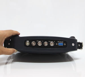
- Dual-channel simultaneous data collection
- Hardware envelop demodulation for bearing and gear diagnosis
- Transfer function for measuring natural frequency
- Waveform and spectrum display by large LCD
- Storage of vibration values and vibration waveform
Operation condition
- Temperature range: from 5°C to 50°C
- Relative humidity: < 85%, unsaturated
- Without caustic gases
- Without strong electric-magnetic field & strong impact
Safety
The HG904 are not permitted to contact with running part of machine.


Specifications:
- Rotation speed range for dynamic balancing: 70-60,000 r/min
- Auto-range and manual-range selectable
- Measuring accuracy of vibration: 5 %
l Sensors: Piezoelectric accelerometer, Magnetoelectricity velocity, Eddy displacement and etc.
- 8th-order ellipse anti-aliasing filter, RPM band-pass filter
- Input signal: Accelerometer, and voltage
- Amplitude spectrum analysis: 100 lines to 400 lines (zoom), Hanning windowed
- Frequency span of spectrum analysis: 100, 200, 500, 1K, 2K, 5K, 10KHz(only for 1-channel sampling)
- Data storage: 400 waveforms of 1024-points and 400 data sets
- Amplitude ranges & Frequency Response for overall vibration measurement:
| |
Amplitude ranges |
Frequency Response |
| Displacement |
0.003 – 5 mm peak-peak |
10 – 500 Hz |
| Velocity |
0.2 – 200mm/s true RMS |
10 – 1000 Hz |
| Acceleration |
0.5 – 250m/s2 peak |
20 – 5000 Hz |
| Envelope |
0.1 – 20unit true RMS |
5-1000Hz from 15-40 KHz |
| Voltage |
0.1 – 10V peak-peak |
10 – 10000 Hz |
- Notepad: 10 condition codes for visual inspection
- Output: USB for communication with PC
- Power: Ni-MH rechargeable battery for 8 hours continuous operation, low battery warning
- Operating Environment: 0~55 oC, 90% humidity non-condensing
- Rotating speed measurement with photocell sensor
- Dynamic Range: 60dB with 48dB adjustable gain range
- Dimensions: 21×13×4 cm; Weight: 1.2 kg (Include batteries)

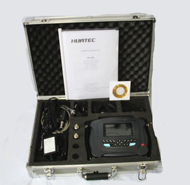
HG904 Pack List
HG904 Vibration Data Collector 1
Accelerometer 2
Magnetic Mount 2
Steel Extension Probe 1
Battery Charger 1
Accelerometer Cable 3
RS232c Communication Cable 1
Balancing Module 1
Tacho/Trigger Sensor and cable 1
Reflector Paper set 1
Quick Start Guide 1
Software CD 1
Certificates of HG904 and sensors 3
Carrying Case 1
BALANCE PRINCIPLES
What is 1-plane rotor imbalance?
Rigid rotor works under the speed far less than its first-order critical rotate speed and its deformation can be neglected. When the quality of the rigid rotor nearly focuses on a disc, namely the ratio of its axial length and its diameter is less than 0.5; we can do 1-plane balance on it and gain satisfactory result.
But for the flexible rotor, the deformation cannot be neglected. So its method of balance differs from rigid rotor. However, the rotor with single imbalance plane can also be balanced according to the method of 1-plane balance of rigid rotor. For above, whether the rigid or flexible rotor, its quality of imbalance always focuses on one disc, so both of them can be balanced according to the method of 1-plane rotor balance. In the plant and manufactory, such rotating machines are ubiquitous, such as pump, ventilator etc.
Principle of 1-Plane Balancing
HG904’s 1-plane balance adopts the method of influence coefficient, which is also called balance method of 1-plane phase measuring. Just as its name implies, it’s desirous to do the measurement with the phase of rotation-speed vibration when measuring the vibration amplitude of rotor. The rotation-speed vibration can be indicated as vector. The process of 1-plane balance is as follows:
- Measure and gain the initial rotation-speed vibration vector (A0) under the normal operation condition.
- Load the proper trial mass (M) on the rotor and then measure vibration vector (A01) under the condition of the same rotate speed.
- Calculate the balance mass (Q) which should be load on the rotor according to the following formula:
Q = - M x A0 / (A01 – A0)
During the balancing, all the vibration should be measured under the same rotate speed because of the imbalance force of rotor relates with the rotate speed.
Principle of 2-planes balancing
Almost all the balance of single span rotor can be achieved through the method of 2-planes dynamic balance. As a matter of fact, 1-plane dynamic balance is only one special example of 2-planes dynamic balance.
When doing 2-planes dynamic balance, two planes of adding mass and two points of vibration measure are needed. HG904’s 2-planes dynamic balance also adopts the method of influence coefficient. But the difference from 1-plane dynamic balance is that the vibration of two measurement points should be measured when adding trial-mass to one of the planes. That’s so-called interact effect. 2-planes dynamic balance has four influence coefficients.
The steps to do 2-planes dynamic balance is as followings:
- Measure initial value of two measurement points.
- Load trial mass to first plane, then measure the vibration of two measurement points respectively.
Load trial mass to second plane, and then measure the vibration of two measurement points respectively.
- Get conclusion of the correction mass.
If the influence coefficient is known, it can be input directly and the above step (2) can be omitted.
APPENDIX
BALANCE GRADE OF RIGID ROTORS
(Abstracted from ISO 1940/1-1986 Requirement of balance grade of rigid rotors—machine vibration)
| Balance grade |
G
(mm/s)
|
Examples of the rotor type |
| G4000 |
4000 |
Rigidly fixed crooked-axis transmission set of low-RPM diesel engine, with odd amount of gases, specially used for ship |
| G1600 |
1600 |
Rigidly fixed crooked-axis transmission set of great 2-stroke engine. |
| G630 |
630 |
Rigidly fixed crooked-axis transmission set of great 4-stroke engine
Flexibly fixed crooked-axis transmission set of diesel engine specially used for ship
|
| G250 |
250 |
Rigidly fixed crooked-axis transmission set of high-RPM 4-gas diesel engine. |
| G100 |
100 |
Crooked-axis transmission set of high-RPM diesel engine with 6 or more gases
The whole engine of a truck or an auto (diesel or gas engine)
|
|
G40
|
40
|
Wheels, flange, transmission axis of an auto
Flexibly fixed crooked-axis transmission set of high-RPM 4-stroke engine with 6 or more gases
Crooked-axis transmission set of an auto, a truck
|
|
G16
|
16
|
Transmission axes with special requirements (axle-rotating axes, all-way axes)
Parts of crusher
Parts of agricultural machine
Engines of auto, truck and locomotive (the whole of diesel or gas engine)
Crooked-axes transmission set of provider with 6 or more gases under special conditions.
|
|
G6.3
|
6.3
|
Parts of master engine
Tub wheel of centrifugal machine
Roller of paper-machine, roller of presswork
Fan
Rotor of assembled aviation turbo line
Flywheel
Pump wheel
Parts of lathe and general mechanical
General or great armature without special requirements (the height of electricity’s axes center is at most 80mm)
Small armature which is often yielded a great deal and used under the conditions of not being sensitive to vibration or there is sets for isolate vibration. The whole of a engine with special demands.
|
|
G2.5
|
2.5
|
Rigid rotor of turbine generator
Disks and drums of a computer
Turbo compressor
Transmission set of a lathe
General or great armature with special demands
|
|
G1
|
1
|
Transmission set of tape recorder and gramophone (photograph)
Transmission set of grinding machine.
Small armature with special demands
|
|
G0.4
|
0.4
|
Main axes, grinding wheel and armature of a precise grinding machine
Gyroscope
|

 Your message must be between 20-3,000 characters!
 Please check your E-mail!
  Your message must be between 20-3,000 characters!
 Please check your E-mail!
